A topographical survey is a measured drawing of a piece of land that records its shape, levels and physical features to scale. It captures what is actually on and around a site — the ground heights, boundaries, buildings, trees, drainage, services and hard surfaces — so that designers, engineers and planners can work from accurate dimensions rather than guesswork. In short, it is the factual baseline that every later drawing is built upon.
What a topographical survey records
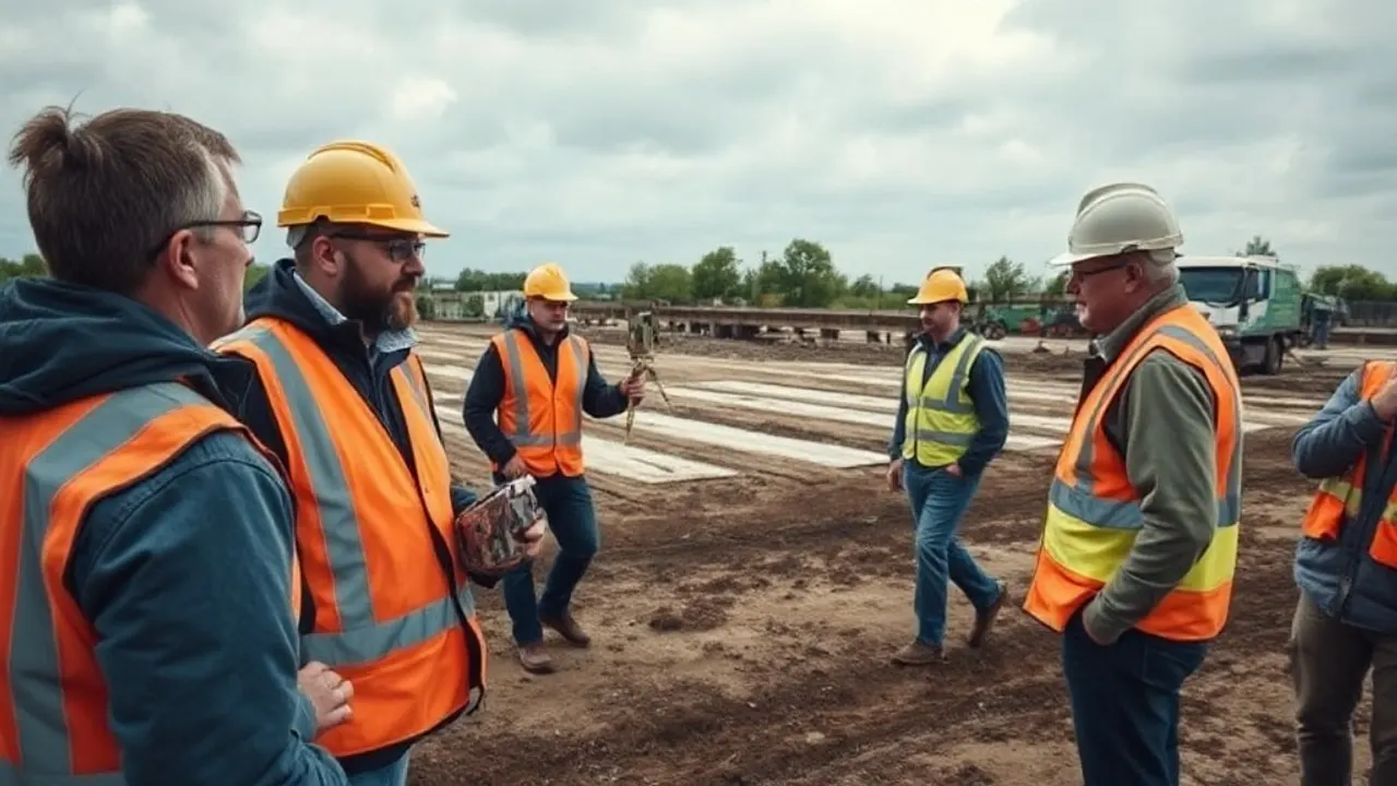
The survey produces a plan, and usually a set of levels, showing the existing condition of a site at the moment it was measured. It is concerned with measurable reality, not with what is proposed. A surveyor walks the site and records the position and height of every relevant feature, then plots these into a scaled drawing that an architect or engineer can open in CAD (computer-aided design) software.
Typical content includes:
- Ground levels across the site, shown as spot heights and contours
- Boundaries and any walls, fences or hedges that mark them
- Buildings and structures, with footprints and often ridge and eaves heights
- Hard surfaces such as roads, paths, kerbs and parking areas
- Trees, with trunk position, canopy spread and an indication of size
- Visible drainage and services — manhole covers, gullies, inspection chambers, stop taps and overhead cables
- Watercourses, ponds and other natural features
The level of detail and the area covered are set out in a brief before work starts. A survey can be limited to the plot itself, or extended to take in adjacent land, the road frontage and neighbouring buildings where these affect a design. Manhole covers are commonly lifted to record invert levels — the depth of the pipe inside — but only when access is agreed in advance, since that involves entering the drainage system.
When a survey is needed
A topographical survey is a measured drawing of a piece of land that records its shape, levels and physical features to scale.
A topographical survey is usually one of the first things commissioned once a project becomes serious. Any scheme that involves building, extending, levelling or draining land benefits from an accurate base, and most design professionals will ask for one before producing proposals. Working from an out-of-date or rough plan tends to cause problems later, when measurements taken on site fail to match the drawings.
Common situations where a survey is relied upon include:
- New buildings, extensions and conversions, where the design must sit correctly on the existing ground
- Planning applications, which often require an existing site plan drawn to scale
- Drainage and groundworks design, which depend on accurate levels to make water flow the right way
- Landscaping and earthworks, where cut-and-fill volumes are calculated from existing and proposed levels
- Road, access and car park layouts, which need precise gradients and falls
- Boundary and access disputes, where an independent measured record can clarify what is actually on the ground
The timing matters. A survey carried out early gives designers room to respond to the site as it really is, rather than reworking a scheme once an awkward slope or an unexpected drain comes to light. On sites that change — where vegetation is cleared or ground is disturbed — a survey may need to be repeated or updated, because it only describes conditions on the day it was taken.
For some projects a topographical survey alone is not enough. It records what is visible above ground, so buried services, ground conditions and below-surface structures generally call for separate investigations such as a utility survey or trial holes. It is worth being clear at the outset about what falls inside the brief and what does not.
Levels, contours and surface detail
Height information is the part of a topographical survey that distinguishes it from a simple line plan. The surveyor records a network of spot levels — individual points with a measured height — spread closely enough to describe how the ground rises and falls. From these points, software interpolates contours: lines that join points of equal height, usually drawn at a fixed interval such as every 0.25 or 0.5 metres. Closely spaced contours indicate steep ground; widely spaced ones indicate gentle slopes or flat areas.
Together, spot levels and contours let a designer understand the lie of the land without visiting it, and let an engineer work out gradients, drainage falls and the volume of earth that would need to be moved. Levels are also taken at critical features — thresholds, gully tops, kerb lines and tree bases — because these fixed points often govern how a design must work.
Alongside the levels, the survey captures site detail: the plan position of every feature, drawn to scale and shown with consistent symbols and line styles so the result is readable. The combination of accurate detail and accurate heights is what makes the drawing a reliable foundation for design work.
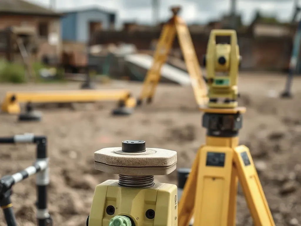
Levels need a reference, and there are two common approaches. A survey can be tied to an arbitrary datum — a local reference point given an assumed height — which is simple and adequate for a self-contained project. More often, it is tied in to the national framework so that heights relate to Ordnance Survey Newlyn datum, the standard reference for height in mainland Great Britain, and positions relate to the National Grid. This Ordnance Survey grid tie-in means the survey sits correctly within the wider mapped landscape, which matters when a project must align with neighbouring sites, existing infrastructure or published mapping. A GNSS receiver — satellite positioning equipment — is typically used to establish the connection on site.
The finished survey is usually supplied as a CAD file and a PDF, drawn at a stated scale and accuracy. Anyone receiving one should confirm the datum used, the date of measurement, the area covered and the conventions applied, so that everyone working from it understands exactly what it represents and what its limits are.

Reviewed: June 2026